Introduction to SIM900 GSM/GPRS Shield with Arduino
The SIM900 GSM/GPRS Shield is a powerful add-on module that brings cellular communication capabilities to your Arduino projects. This comprehensive guide walks you through everything you need to know to get started with sending and receiving SMS messages and making phone calls with Arduino.
What is the SIM900 GSM/GPRS Shield?
GSM (Global System for Mobile Communications) is the global standard for mobile communications, while GPRS (General Packet Radio Service) is a mobile data service available on 2G and 3G cellular networks. The SIM900 GSM/GPRS Shield combines these technologies into a single Arduino-compatible board.
Internet Connectivity
Connect to the Internet over GPRS networks where WiFi isn't available, enabling remote data transmission.
SMS Communication
Send and receive text messages for alerts, commands, or data exchange with your Arduino projects.
Voice Calling
Make and receive phone calls, transforming your Arduino into a communication device.
Global Compatibility
Quad-band support (850/900/1800/1900 MHz) ensures operation in most countries with GSM networks.
Practical Applications

The GSM/GPRS Shield opens up numerous possibilities for Arduino projects:
- Remote Control Systems: Send an SMS to turn appliances on or off from anywhere
- Security Notifications: Receive instant alerts when sensors detect motion, water leaks, or intrusions
- Data Monitoring: Get periodic SMS updates with sensor readings like temperature, humidity, or energy usage
- GPS Tracking: Combine with GPS modules for location-based applications and tracking
- Industrial Monitoring: Remote equipment status monitoring and fault alerts
Key Features and Specifications
Core Module
Based on SIM900 module from SIMCOM with control via AT commands
Compatibility
Works with Arduino Uno and similar boards with standard pin headers
I/O Capabilities
12 GPIO pins, 2 PWM outputs, and built-in ADC of the SIM900 module
Real-Time Clock
Includes holder for 3V CR1220 battery for timekeeping when powered off
Preliminary Setup Requirements
1 SIM Card Preparation
Before using your SIM900 GSM/GPRS Shield, you need to properly prepare your SIM card:
- Use a Prepaid SIM Card: For testing, use a prepaid plan with unlimited SMS to avoid unexpected charges
- Disable PIN Lock: Insert the SIM in a smartphone and disable the PIN requirement in security settings
- Check Network Coverage: Ensure you have GSM coverage (2G network) in your area
- SIM Size: The shield uses standard SIM size (not micro or nano - adapters may be needed)
2 Power Supply Requirements
The SIM900 GSM/GPRS Shield has specific power requirements for reliable operation:
- Recommended: 5V power supply capable of providing 2A current
- Alternative Options: 9V at 1A or 12V at 1A
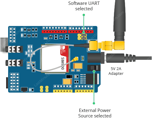
- Toggle Switch: Move to external power position when using dedicated power supply
- Power Jack: Standard DC power jack for external power connection
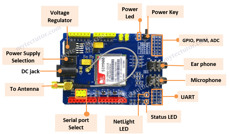
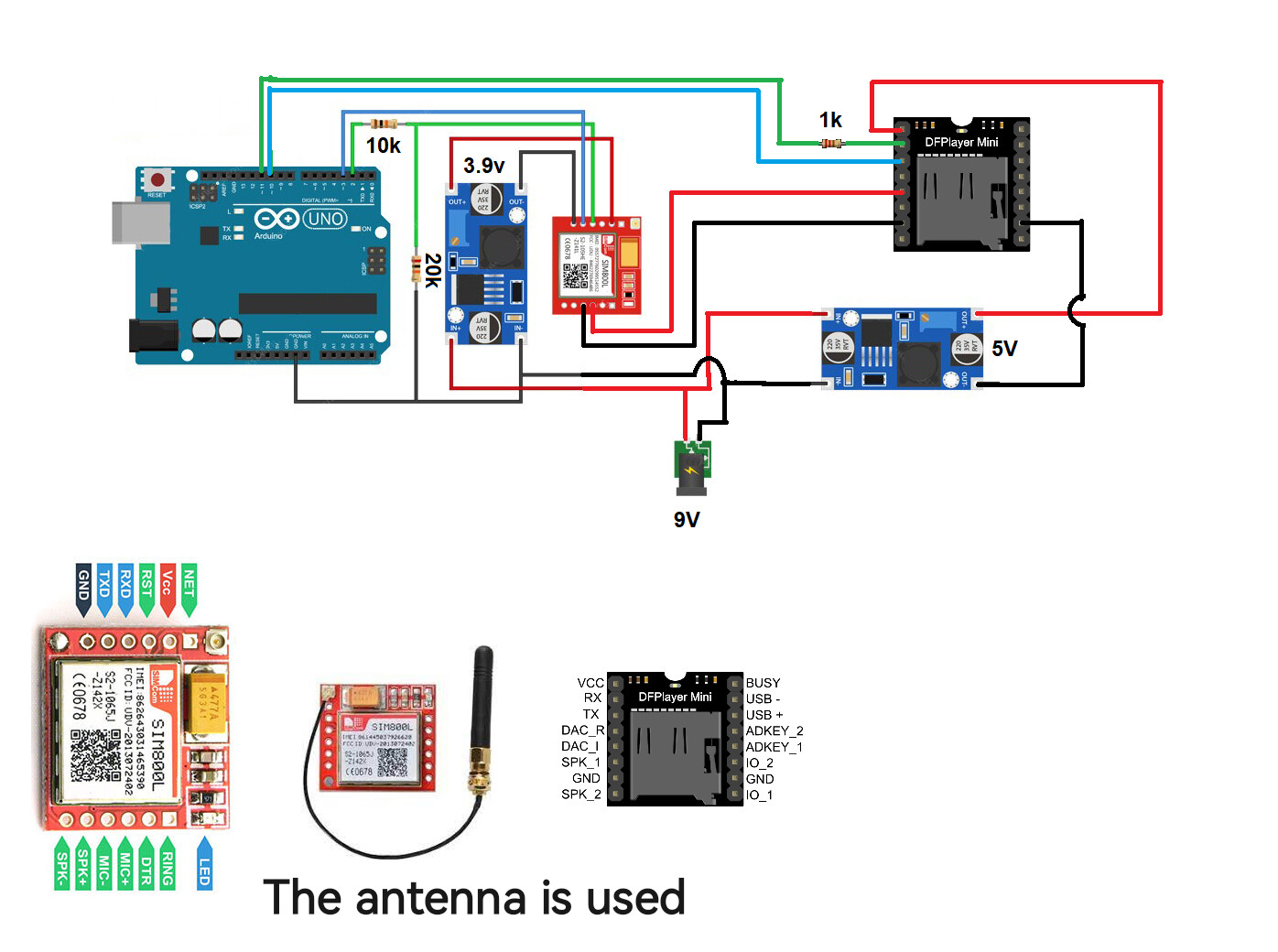
Hardware Overview and Connection
3 Getting Started Steps
- Insert SIM Card: Place your prepared SIM card into the holder on the back of the shield
- Connect Antenna: Attach the provided antenna to the U.FL connector for optimal signal
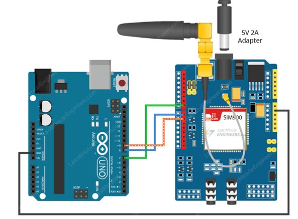
- Configure Serial Port: Set jumpers for software serial communication (typically pins 7 and 8)
- Power Up: Connect your 5V, 2A power supply and flip toggle to external power position
- Turn On Shield: Press and hold power button for 2 seconds until Status LED lights up
- Network Connection: NetLight LED blinks every 800ms while searching, then every 3 seconds when connected
Essential AT Commands for SIM900
AT commands (Attention commands) are text-based instructions used to control the SIM900 module. Here are the most essential commands:
| Command | Description | Usage |
|---|---|---|
| AT | Test command to check communication | Should return "OK" if working |
| AT+CMGF=1\r | Set module to text mode for SMS | Required before sending/receiving SMS |
| AT+CMGS="PHONE_NUMBER" | Send SMS to specified number | Use international format (+country code...) |
| AT+CMGR=1\r | Read first SMS from inbox | Returns message content and metadata |
| ATD+PHONE_NUMBER | Dial a phone number | Initiates voice call to specified number |
| ATH | Hang up active call | Terminates ongoing voice call |
Testing the Shield with FTDI Programmer
4 Initial Testing Procedure
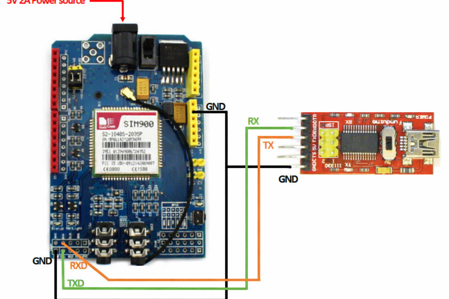
Before integrating with Arduino, test the shield independently using an FTDI programmer:
- Connect FTDI Programmer: TX to shield RX, RX to shield TX, ground to ground
- Power Separately: Use external 5V, 2A power supply (don't use FTDI for power)
- Open Arduino IDE Serial Monitor: Select correct COM port, set to 19200 baud, Carriage return
- Send Test Command: Type "AT" and press Enter - should receive "OK" response
Sending SMS with Arduino Code Example
5 Complete SMS Sending Code
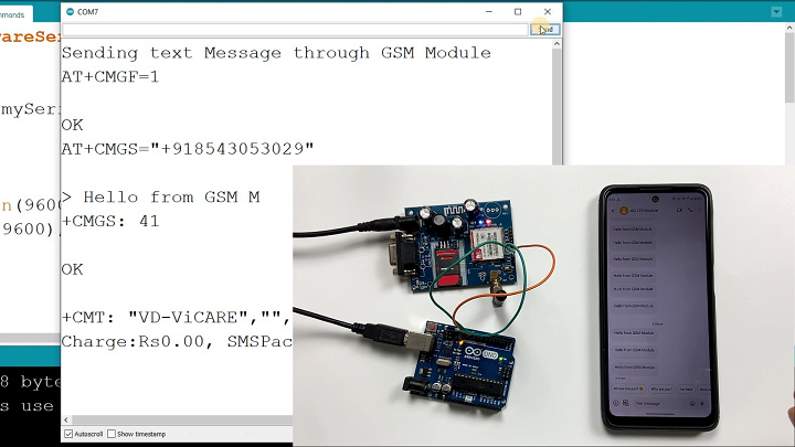
Here's the complete code to send an SMS using your Arduino and SIM900 shield:
#include// Configure software serial port SoftwareSerial SIM900(7, 8); void setup() { // Arduino communicates with SIM900 at 19200 baud SIM900.begin(19200); // Give time for network registration delay(20000); // Send the SMS sendSMS(); } void loop() { // Empty loop for this example } void sendSMS() { // AT command to set SIM900 to SMS mode SIM900.print("AT+CMGF=1\r"); delay(100); // REPLACE WITH RECIPIENT'S MOBILE NUMBER // USE INTERNATIONAL FORMAT SIM900.println("AT+CMGS=\"+12345678901\""); delay(100); // REPLACE WITH YOUR MESSAGE CONTENT SIM900.println("Hello from Arduino with SIM900!"); delay(100); // End AT command with Ctrl+Z (ASCII 26) SIM900.println((char)26); delay(100); SIM900.println(); // Give module time to send SMS delay(5000); }
Code Explanation: This example uses SoftwareSerial on pins 7 and 8 to communicate with the SIM900 shield. The sendSMS() function configures the module for text messages, specifies the recipient number, sends the message content, and terminates with Ctrl+Z (ASCII 26).
Receiving SMS with Arduino
6 SMS Reception Code Example
To read incoming SMS messages, upload this code to your Arduino:
#includeSoftwareSerial SIM900(7, 8); char incoming_char = 0; void setup() { SIM900.begin(19200); Serial.begin(19200); // For serial monitor delay(20000); // Network registration time // Set SIM900 to SMS mode SIM900.print("AT+CMGF=1\r"); delay(100); // Configure new message indications SIM900.print("AT+CNMI=2,2,0,0,0\r"); delay(100); } void loop() { // Display incoming SMS on serial monitor if(SIM900.available() > 0) { incoming_char = SIM900.read(); Serial.print(incoming_char); } }
How It Works: This code configures the SIM900 module to forward received SMS directly to the serial output. When a message arrives, it's displayed character-by-character in the Arduino Serial Monitor. You can extend this code to parse specific information or trigger actions based on message content.
Making and Receiving Phone Calls
7 Phone Call Functionality
The SIM900 GSM/GPRS Shield supports full voice call functionality. For phone calls to work properly:
- Audio Connections: Connect a microphone to the MIC jack and headphones/speaker to the SPK jack
- Call Initiation: Use
ATD+PHONE_NUMBER;command to dial a number - Call Answering: Use
ATAcommand to answer incoming calls - Call Termination: Use
ATHcommand to hang up active calls
Advanced Feature: Automatic Power Control
8 Software-Controlled Power Management
Instead of manually pressing the power button, you can enable software-controlled power management:
- Hardware Modification: Solder a bridge across the R13 resistor pads on the shield
- Connect to Arduino: Run a wire from shield D9 to Arduino digital pin 9
- Add to Setup: Include this code in your
setup()function:
// Automatic power-on sequence
pinMode(9, OUTPUT);
digitalWrite(9, HIGH);
delay(1000);
digitalWrite(9, LOW);
This sequence simulates pressing the physical power button for one second, eliminating manual intervention and enabling completely autonomous systems.
Troubleshooting Common Issues
No Response to AT Commands
Solution: Check power supply, verify 19200 baud rate, inspect all connections, test with FTDI programmer.
SIM Card Not Detected
Solution: Reinsert SIM, ensure PIN lock is disabled, try different SIM card, check for damaged contacts.
Poor Signal Strength
Solution: Reposition antenna, move to area with better GSM coverage, verify carrier supports 2G.
SMS Sending Failures
Solution: Check number format (international), verify network registration, ensure adequate delays between commands.
Next Steps and Project Ideas
With the foundation established in this guide, consider these advanced project directions:
- GPRS Data Transmission: Send sensor data to web servers via GPRS internet connection
- GPS Tracker: Combine with GPS module to create a location tracking device
- Home Security System: Build a comprehensive security system with SMS alerts and remote control
- Industrial Monitor: Create equipment monitoring systems with automated fault reporting
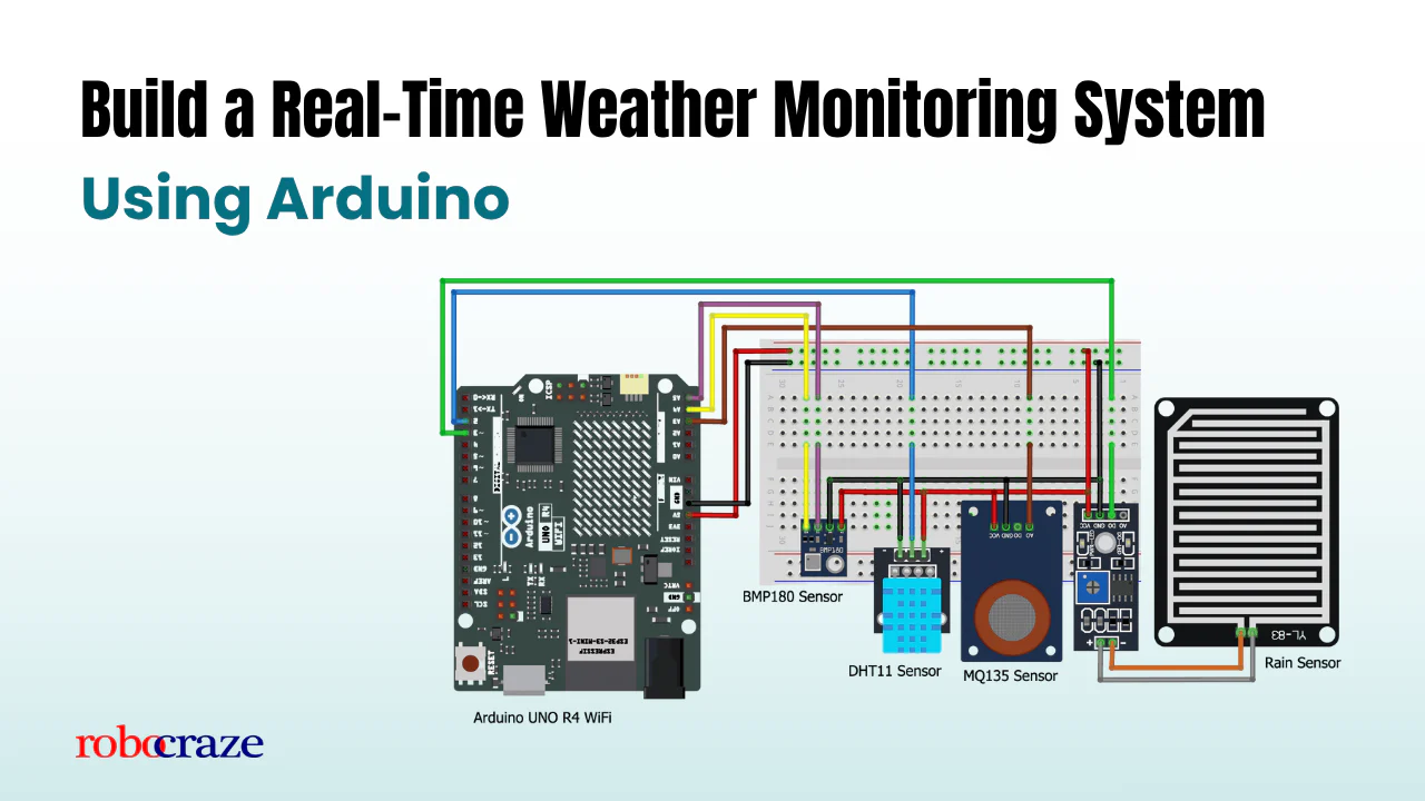
- Weather Station: Build a remote weather station that texts daily reports