Understanding ESP32 GPIO Pinout Fundamentals
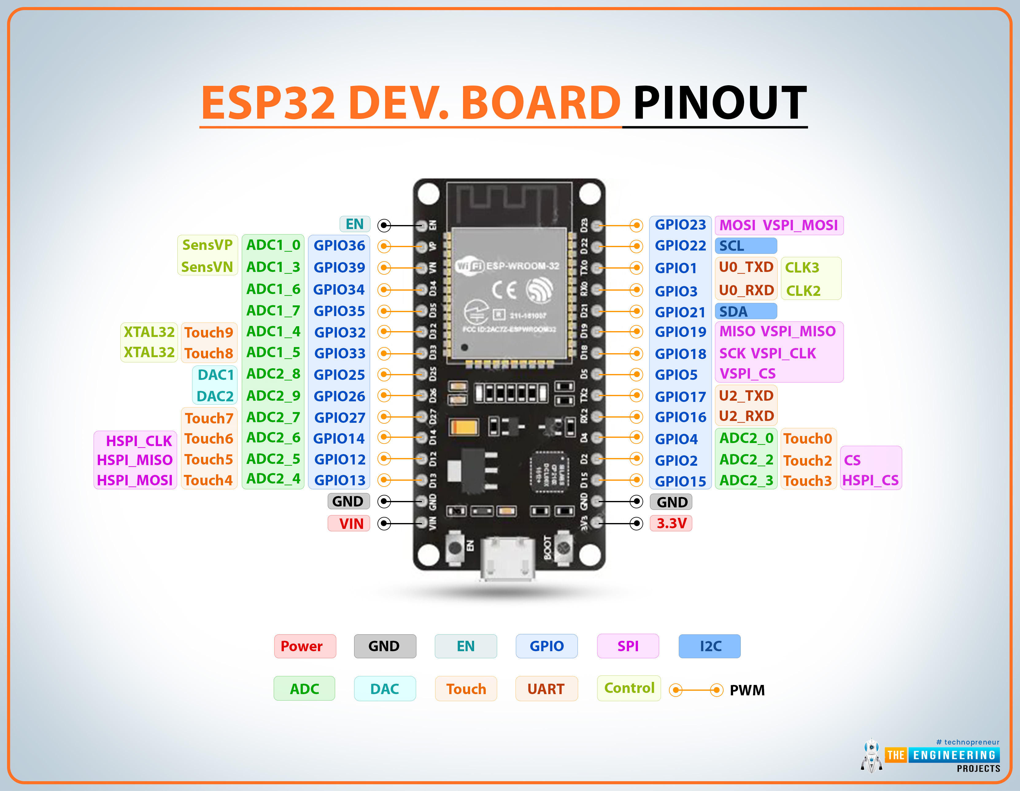
The ESP32 microcontroller comes with an impressive array of 48 pins offering multiple functions, but this abundance can be confusing for developers. Not all pins are exposed in every ESP32 development board, and some pins come with critical restrictions that can trap unwary makers.
This comprehensive guide answers the essential questions every ESP32 developer faces: What pins should you use for your projects? Which ones should you avoid entirely? We'll cover the ESP32's multiplexing capabilities, special function pins, and provide practical advice for both beginners and experienced developers.
ESP32 GPIO Quick Reference Table
This at-a-glance reference table shows which GPIOs are safe for input/output operations and which require special attention:
| GPIO | Input | Output | Notes |
|---|---|---|---|
| 0 | Pulled Up | OK | Outputs PWM at boot; must be LOW for flashing |
| 1 | TX Pin | OK | Debug output at boot |
| 2 | OK | OK | On-board LED; must be floating/LOW for flashing |
| 3 | OK | RX Pin | HIGH at boot |
| 4 | OK | OK | General purpose |
| 5 | OK | OK | PWM at boot; strapping pin |
| 6-11 | ✗ | ✗ | Connected to integrated SPI flash (AVOID) |
| 12 | OK | OK | Boot fails if pulled HIGH; strapping pin |
| 13-23 | OK | OK | General purpose (except as noted) |
| 25-27 | OK | OK | General purpose |
| 32-33 | OK | OK | General purpose |
| 34-39 | OK | Input Only | No internal pull-up/down resistors |
Critical GPIO Categories and Restrictions
1 Input-Only Pins (GPIO 34-39)
GPIOs 34, 35, 36, and 39 function exclusively as input-only pins. These pins:
- Cannot be configured as outputs under any circumstances
- Lack internal pull-up or pull-down resistors (add external if needed)
- Are ideal for reading sensors, buttons, or analog signals
- Can serve as external wake-up sources from deep sleep
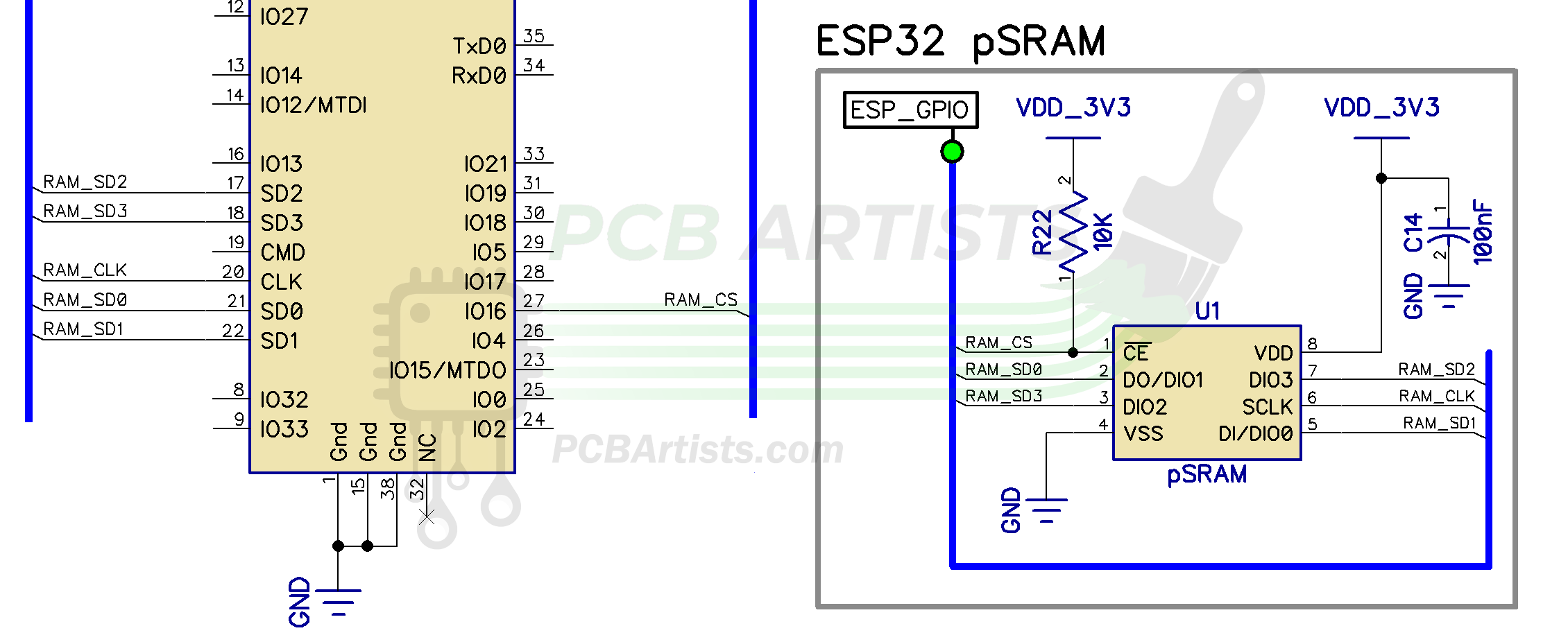
2 SPI Flash-Connected Pins (GPIO 6-11)
GPIOs 6 through 11 connect directly to the integrated SPI flash memory. While some development boards expose these pins, using them for other purposes is strongly discouraged because:
- They can interfere with flash operations during boot
- May cause system instability or boot failures
- Could corrupt the firmware if misused
3 Capacitive Touch GPIOs
The ESP32 includes 10 internal capacitive touch sensors that can detect human touch without physical contact. These GPIOs can:
- Replace mechanical buttons with touch interfaces
- Wake the ESP32 from deep sleep
- Detect proximity through capacitive changes
The touch-sensitive GPIOs are: T0 (GPIO 4), T1 (GPIO 0), T2 (GPIO 2), T3 (GPIO 15), T4 (GPIO 13), T5 (GPIO 12), T6 (GPIO 14), T7 (GPIO 27), T8 (GPIO 33), and T9 (GPIO 32).
Analog and Digital Conversion Capabilities
ADC vs DAC Overview
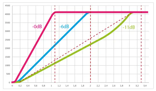
The ESP32 features 18 ADC channels (12-bit) and 2 DAC channels (8-bit). ADC2 channels conflict with Wi-Fi operation, so plan your analog readings accordingly.
Analog-to-Digital Converter (ADC) Channels
The ESP32's 12-bit ADC provides 18 input channels with resolution from 0-4095 (0V to 3.3V):
                    // ADC1 Channels (8 channels, work with Wi-Fi)
                    ADC1_CH0 → GPIO 36    ADC1_CH4 → GPIO 32
                    ADC1_CH1 → GPIO 37    ADC1_CH5 → GPIO 33
                    ADC1_CH2 → GPIO 38    ADC1_CH6 → GPIO 34
                    ADC1_CH3 → GPIO 39    ADC1_CH7 → GPIO 35

                    // ADC2 Channels (10 channels, conflict with Wi-Fi)
                    ADC2_CH0 → GPIO 4     ADC2_CH5 → GPIO 12
                    ADC2_CH1 → GPIO 0     ADC2_CH6 → GPIO 14
                    ADC2_CH2 → GPIO 2     ADC2_CH7 → GPIO 27
                    ADC2_CH3 → GPIO 15    ADC2_CH8 → GPIO 25
                    ADC2_CH4 → GPIO 13    ADC2_CH9 → GPIO 26
Digital-to-Analog Converter (DAC)
For analog output, the ESP32 provides two 8-bit DAC channels:
- DAC1: GPIO 25
- DAC2: GPIO 26
These channels are perfect for audio applications, generating analog voltage references, or controlling devices that require true analog signals rather than PWM simulation.
Communication Protocol Default Pin Assignments
| Protocol | Default Pins | Remappable | Notes |
|---|---|---|---|
| I2C | SDA: GPIO 21 SCL: GPIO 22 |
Yes | Use Wire.begin(SDA, SCL) to remap |
| SPI (VSPI) | MOSI: 23, MISO: 19 CLK: 18, CS: 5 |
Yes | Default SPI port |
| SPI (HSPI) | MOSI: 13, MISO: 12 CLK: 14, CS: 15 |
Yes | Secondary SPI port |
| UART0 | TX: GPIO 1 RX: GPIO 3 |
Yes | Default Serial Monitor |
| UART1 | TX: GPIO 10 RX: GPIO 9 |
Must Remap | Conflicts with SPI flash |
| UART2 | TX: GPIO 17 RX: GPIO 16 |
Yes | General purpose UART |
Special Function GPIOs
4 RTC GPIOs for Deep Sleep
The RTC GPIO subsystem enables ultra-low-power deep sleep functionality. These pins can wake the ESP32 from deep sleep:
                        // Main RTC GPIOs for deep sleep wake-up
                        RTC_GPIO0  → GPIO 36   RTC_GPIO9  → GPIO 32
                        RTC_GPIO3  → GPIO 39   RTC_GPIO10 → GPIO 4
                        RTC_GPIO4  → GPIO 34   RTC_GPIO11 → GPIO 0
                        RTC_GPIO5  → GPIO 35   RTC_GPIO12 → GPIO 2
                        RTC_GPIO6  → GPIO 25   RTC_GPIO13 → GPIO 15
                        RTC_GPIO7  → GPIO 26   RTC_GPIO14 → GPIO 13
                        RTC_GPIO8  → GPIO 33   RTC_GPIO15 → GPIO 12
5 Strapping Pins
Strapping pins control the ESP32's boot mode and initial configuration:
- GPIO 0: Must be LOW to enter bootloader mode
- GPIO 2: Must be floating or LOW during boot
- GPIO 5: Must be HIGH during boot
- GPIO 12: Must be LOW during boot
- GPIO 15: Must be HIGH during boot
Most development boards handle these automatically, but peripherals connected to strapping pins can interfere with programming and reset functions.
6 Pins with Special Boot Behavior
Some GPIOs exhibit specific behaviors during boot/reset that can affect connected peripherals:
- GPIO 1: Serial debug output at boot
- GPIO 3: HIGH at boot
- GPIO 5, 14, 15: Output PWM signals at boot
- GPIO 6-11: Active with SPI flash (avoid)
Best Practices and Pro Tips
ESP32 GPIO Best Practices
- Always check boot behavior before connecting active components
- Avoid GPIO 6-11 completely for external circuitry
- Use ADC1 channels when Wi-Fi is active
- Remember input-only limitations of GPIO 34-39
- Isolate strapping pins from peripherals if experiencing programming issues
- Implement debouncing for buttons on pins with boot PWM output
- Respect 3.3V limits - ESP32 GPIOs are not 5V tolerant
- Stay under 40mA per GPIO pin (absolute maximum)
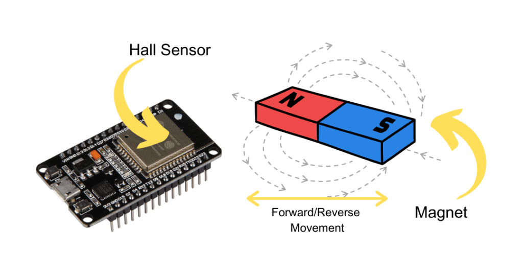
ESP32 Built-In Sensors
Beyond the GPIO functions, the ESP32 includes a built-in hall effect sensor that detects changes in magnetic fields without requiring external components. This sensor isn't tied to a specific GPIO but is accessed through specialized library functions.
Conclusion
Mastering the ESP32 pinout unlocks this powerful microcontroller's full potential while avoiding common pitfalls. Remember these key takeaways:
- Avoid GPIO 6-11 - they're reserved for internal flash
- GPIO 34-39 are input-only with no pull-up/down resistors
- ADC2 conflicts with Wi-Fi - plan your analog readings accordingly
- Mind the strapping pins during circuit design
- Leverage multiplexing capability to optimize pin assignments
With this comprehensive reference, you're equipped to make informed decisions about ESP32 GPIO usage, whether you're prototyping on development boards or designing custom PCB implementations. The ESP32's flexible pin configuration allows creative solutions to complex interfacing challenges once you understand the boundaries and best practices.