Why Use GSM with the ESP32?
In an interconnected world, sometimes Wi-Fi and Bluetooth just aren't enough. What if your ESP32 project needs to send an alert from the middle of a field, monitor a remote cabin, or notify you of a power outage when the internet is down? The answer lies in the global, ubiquitous cellular network.
This comprehensive tutorial will guide you through using the SIM800L GSM module with the ESP32 to send SMS text messages. It's a powerful skill that opens up a world of remote, off-grid IoT projects. We'll cover the hardware connections, library setup, and provide you with robust code examples to get your project texting in no time.
The ESP32 is a powerhouse with Wi-Fi and Bluetooth, but its range is limited to local networks. A GSM module like the SIM800L acts as a cellular modem, giving your project access to mobile networks. This means you can send and receive data—starting with SMS—from virtually anywhere you have a cellular signal. Think of it as giving your ESP32 a "dumb phone" to communicate with the world.
Key Applications:
- Remote Sensor Alerts (intrusion, water leak, temperature)
- Industrial Equipment Monitoring
- GPS Tracker Notifications
- Smart Agriculture Updates
- Fallback communication system when Wi-Fi fails
Components Needed
Essential Components
- ESP32 Development Board (e.g., ESP32 DEVKIT DOIT)
- SIM800L GSM Module (3.2V-4.8V version, ideally with a breakout board)
- Micro SIM Card (activated, with credit, and not PIN-locked)
- Power Supply: A stable 4V external power source is critical. Use a 3.7V Lithium Polymer (LiPo) battery or a dedicated 4V/2A DC power supply.
- Peripheral Circuit Components:
- 4x 1kΩ Resistors (for voltage division on the serial lines)
- 1000µF – 2000µF Electrolytic Capacitor (to handle power surges)
- LM2596 DC-DC Buck Converter Module (optional, to step down 5V to 4V if using a USB power bank)
- Jumper Wires and a Breadboard
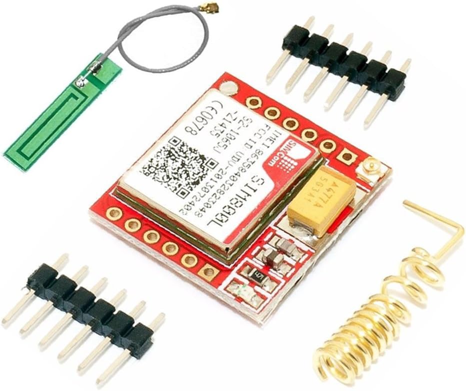
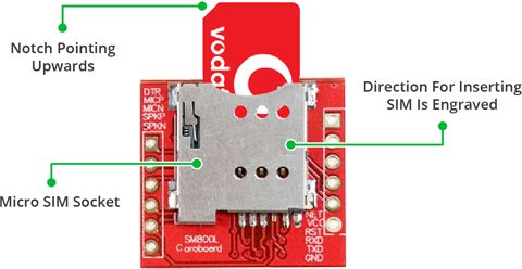
Understanding the SIM800L Module
The SIM800L is a compact and affordable GSM/GPRS module. It operates on frequencies like 850/900/1800/1900MHz, making it compatible with most mobile networks worldwide. The module communicates with the ESP32 using AT commands over a serial interface (UART). This means we "talk" to it by sending specific text commands.
Critical Hardware Notes:
- Power Hungry: The SIM800L can draw brief peaks of up to 2A during network registration or transmission. This is why a robust power supply and a large capacitor across the power lines are non-negotiable to prevent brownouts and resets.
- Logic Levels: While the SIM800L's serial pins (RX/TX) are nominally 3.3V, they are somewhat tolerant. However, a safe and reliable practice is to use a simple voltage divider on the SIM800L's RX line (from the ESP32 TX) to ensure the voltage is within a safe margin.
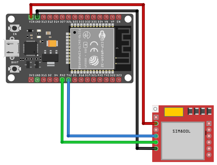
Step-by-Step Wiring: ESP32 to SIM800L
1 The Power Circuit (The Most Important Step)
Proper power supply is critical for the SIM800L to function reliably:
- Connect the positive terminal of your 4V power source (e.g., LiPo battery) to the VCC pin of the SIM800L.
- Connect the negative terminal of the power source to the GND pin of the SIM800L.
- Crucially, also connect this same ground to a GND pin on the ESP32. All grounds must be common.
- Solder or place the 1000µF capacitor directly between the VCC and GND pins of the SIM800L, as close to the module as possible. This acts as a power reservoir.
2 The Serial Communication Circuit
Establishing safe serial communication between ESP32 and SIM800L:
- ESP32 TX2 (GPIO 17) to SIM800L RX: Connect via a voltage divider. Use two 1kΩ resistors. Connect GPIO17 to the first resistor, then connect the junction between the two resistors to SIM800L RX. The other end of the second resistor goes to ground. This scales the 3.3V signal down to approximately 1.65V.
- ESP32 RX2 (GPIO 16) to SIM800L TX: You can connect this directly, as the SIM800L's TX output (~3V) is safe for the ESP32's 3.3V input pin.
- Note: We are using UART2 (pins 16 & 17) to avoid conflict with the default serial used for programming.
3 Control Pins (Optional but Recommended)
For better control over the SIM800L module:
- Connect the SIM800L's RST (Reset) pin to a GPIO on the ESP32 (e.g., GPIO 5). This allows you to hard-reset the module via software if it hangs.
- Connect the SIM800L's PWRKEY pin to another GPIO (e.g., GPIO 4). This lets you power cycle the module programmatically.
Software Setup and Library Installation
4 Prepare Arduino IDE
Ensure your development environment is ready:
- Ensure you have the ESP32 board add-on installed in your Arduino IDE. You can install it via
Tools > Board > Boards Manager...and searching for "ESP32". - Install the Universal Arduino GSM Library. To install it, go to
Sketch > Include Library > Manage Libraries..., search for "GSM", and install the "GSM by M. Dragan" library. This library simplifies AT command handling.
5 SIM Card Preparation
Proper SIM card setup is essential:
- Insert a micro SIM card into the holder on the SIM800L module.
- Ensure the SIM is:
- Active and has network coverage.
- Has sufficient credit to send SMS (if required by your carrier).
- Has the PIN lock disabled in the phone's settings before inserting it. This is often the biggest hurdle for beginners.
The Core Code: Sending an SMS with the ESP32
6 Basic SMS Sender Code
Copy and paste this code into your Arduino IDE. This basic example demonstrates how to initialize the GSM module and send a simple SMS:
                        #include

                        // Define your serial pins for GSM
                        #define GSM_TX_PIN 16
                        #define GSM_RX_PIN 17

                        // Define the phone number and message
                        #define PHONE_NUMBER "+1234567890" // Replace with country code and number
                        #define MESSAGE "Hello from your ESP32 and SIM800L!"

                        // Initialize the library with the correct serial port and baud rate
                        GSM gsmAccess;
                        GSM_SMS sms;

                        void setup() {
                        Serial.begin(115200); // For debugging in the Serial Monitor
                        delay(1000);

                        Serial.println("ESP32 + SIM800L SMS Sender");

                        // Local serial connection to the SIM800L module
                        Serial2.begin(9600, SERIAL_8N1, GSM_RX_PIN, GSM_TX_PIN);

                        // Connection state flag
                        boolean notConnected = true;

                        // Start the GSM module connection
                        Serial.print("Connecting to GSM network...");
                        while (notConnected) {
                            if (gsmAccess.begin(9600, &Serial2) == GSM_READY) {
                            notConnected = false;
                            Serial.println(" CONNECTED");
                            } else {
                            Serial.println(" NOT CONNECTED. Retrying...");
                            delay(1000);
                            }
                        }

                        Serial.println("GSM initialization complete.");

                        // Send the SMS
                        Serial.print("Sending message to ");
                        Serial.println(PHONE_NUMBER);

                        sms.beginSMS(PHONE_NUMBER);
                        sms.print(MESSAGE);

                        if (sms.endSMS()) {
                            Serial.println("SMS sent successfully!");
                        } else {
                            Serial.println("Error sending SMS.");
                        }
                        }

                        void loop() {
                        // Nothing here for this basic example.
                        }
7 Upload and Test
Follow these steps to test your setup:
- Insert your SIM card, apply power to the SIM800L, and wait 20-30 seconds for the network LED to blink every ~3 seconds (indicating registration).
- Upload the code to your ESP32.
- Open the Serial Monitor at 115200 baud.
- Watch the logs. If all goes well, you'll see "SMS sent successfully!" and receive the message on your target phone within a minute.
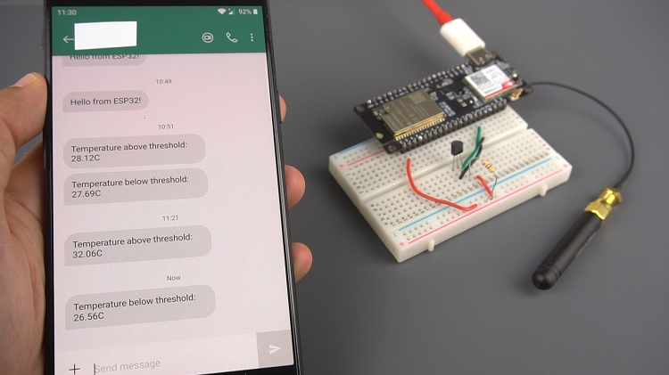
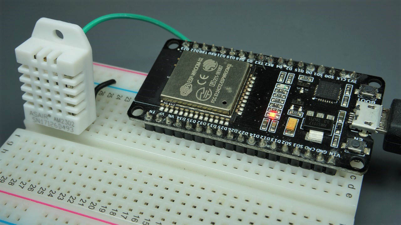
Advanced Project: Temperature Alert System
Let's create a practical project: sending temperature alerts via SMS. We'll combine a DHT22 sensor with our GSM setup.
                        #include
                        #include

                        #define DHTPIN 13
                        #define DHTTYPE DHT22
                        DHT dht(DHTPIN, DHTTYPE);

                        #define GSM_TX_PIN 16
                        #define GSM_RX_PIN 17
                        #define PHONE_NUMBER "+1234567890"

                        GSM gsmAccess;
                        GSM_SMS sms;

                        void setup() {
                        Serial.begin(115200);
                        dht.begin();
                        Serial2.begin(9600, SERIAL_8N1, GSM_RX_PIN, GSM_TX_PIN);

                        boolean notConnected = true;
                        while (notConnected) {
                            if (gsmAccess.begin(9600, &Serial2) == GSM_READY) {
                            notConnected = false;
                            Serial.println("GSM READY");
                            }
                            delay(1000);
                        }
                        }

                        void loop() {
                        delay(30000); // Wait 30 seconds between readings

                        float temperature = dht.readTemperature();
                        float humidity = dht.readHumidity();

                        if (isnan(temperature) || isnan(humidity)) {
                            Serial.println("Failed to read from DHT sensor!");
                            return;
                        }

                        Serial.print("Temperature: "); Serial.print(temperature); Serial.println(" *C");
                        Serial.print("Humidity: "); Serial.print(humidity); Serial.println(" %");

                        // Send an alert if temperature is too high
                        if (temperature > 30.0) {
                            char alertMsg[100];
                            sprintf(alertMsg, "[ALERT] High Temperature Detected: %.1f°C, Humidity: %.1f%%", temperature, humidity);

                            Serial.print("Sending Alert: "); Serial.println(alertMsg);

                            sms.beginSMS(PHONE_NUMBER);
                            sms.print(alertMsg);
                            if(sms.endSMS()) {
                            Serial.println("Alert SMS sent.");
                            }
                        }
                        }
Troubleshooting Common Issues
"NOT CONNECTED" Loop
If the module can't register on the network:
- Check Antenna: Ensure the antenna is properly attached. Signal strength is key.
- Verify SIM: Is it active? Is PIN disabled? Does it have coverage? Try the SIM in a phone first.
- Power Issues: This is the #1 cause. Measure the voltage at the SIM800L's pins during transmission. It must stay above 3.5V. Use a larger capacitor or a better power supply.
Module Resets or Behaves Erratically
Almost certainly a power supply problem. The peak current demand is not being met. Re-evaluate your power source and capacitor.
SMS Fails to Send
The network registration might be incomplete. Add a delay after gsmAccess.begin() or check network status with AT commands manually.
Conclusion
You have now successfully set up a robust ESP32 and SIM800L SMS system. This foundational skill allows your IoT projects to break free from the constraints of local networks and operate globally via cellular connectivity. From here, you can expand to receiving SMS for control, making voice calls, or even using GPRS for lightweight internet data transmission.
Remember, the key to success with the SIM800L is clean, abundant power and a good signal. With those in place, your remote alerting system will be rock-solid.
Congratulations on building your ESP32 cellular communication system! Explore our other tutorials to learn about receiving SMS, making calls, or creating more advanced IoT projects with cellular connectivity.